Installation
Installation in the same way as a conventional underfloor heating system.
The general guidelines and assumptions are the same as for the technical information for underfloor heating systems. Floor ducting to supply individual rooms with supply air is laid underneath the underfloor heating pipe and is therefore integrated into the underfloor heating. In addition the 30/50 mm high ducts are recessed into the insulation so that their upper surface is at the same height as the AIRCONOMY® system module and the AIRCONOMY® folding panel. The heating pipes are fixed with plastic clips on the folding panel or between the pipe-locating profiles of the AIRCONOMY® system module. It is normally not necessary to aspects the floor duct. The arrangement of the heating circuit should be done so that the duct is crossed by the heating pipe. If this is not possible then a clip rail should be glued to the ducting to accept the heating pipes. It is a prerequisite that the building works of plastering and pipe installation for building services have been completed. In winter it is imperative to guarantee no freezing. The plastering walls must be completed right up to the floor slab and the floor slab should be kept free of electrical cables and conduits. If this is not the case then a leveling layer should be put down to create a flat surface to accommodate the heat and noise dampening. This is also necessary when the floor slab shows unacceptable undulations. Before the start of laying, the concrete foundation should the comprehensively swept. Any areas next to earth should be sealed against rising damp. This can be achieved by laying the damp barrier PE 3/300.
INSTALLATION
- Position manifold Cabinet and install primary connections
- Connect heating circuit manifold
- Lay edge insulation strips, system panels and heating pipes
- Wire up controls
It is important that the manifold cabinets, heating circuit manifolds and system controls be designed for optimal integration.
Manifold Cabinet
- Surface-mount and flash-mount cabinets in 3 sizes
- Low build height from 90 mm
Heating circuit manifold
- Model Komfort 90 – 3 (with flowmeter)
- Sizes from 2 – 14 circuits
- For accessories and installation see underfloor heating systems technical information 1.6
Varimatic Controls
- 230 V wired or RF control
- Modular expansion
- For technical details of the components please see underfloor heating systems technical information 1.7
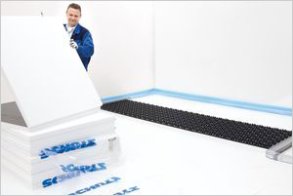
Build-up

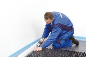
1. Install edge insulation strips

2. Lay sound insulation
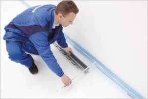
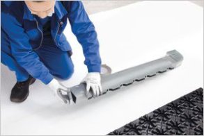
3. Position air outlet manifold

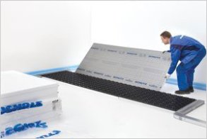
4. Lay distance panel to AIRCONOMY® system module
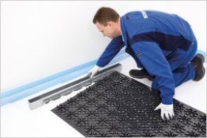
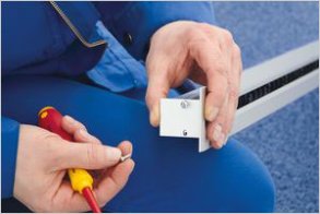
5. Insert AIRCONOMY® system module in air outlet manifold
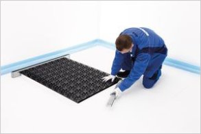
6. Install AIRCONOMY® system module connector
7. Connect 2nd AIRCONOMY® system module
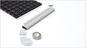
8. Shallow Duct system components in socket joint version

9. Installing shallow duct elbow

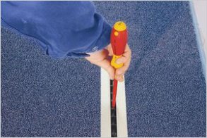
10. Sealing with floor duct tape (fabric lining)
11. Closing the open side of the inlet manifold with lid

12. Secure lid by bending the holding lugs
13. Mounting the inlet manifold onto the AIRCONOMY® system module

14. Mounting and taping the rest of the shallow ducting
15. Mounting and taping the rest of the shallow ducting
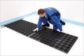
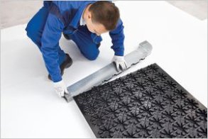
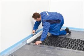
16a. Laying the AIRCONOMY® folding panels
16b. Laying the AIRCONOMY® folding panels
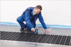
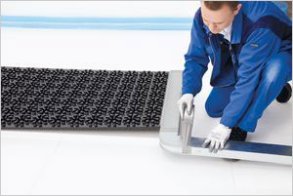
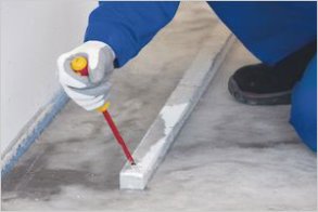
17. Taping the joints and edge insulation strips
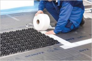
18. Covering the shallow duct with floor duct tape

19. Stage 1 complete

20. Fitting the air outlet screed protector
21. Taping the air outlet screed protector
22. Securing the heating pipe
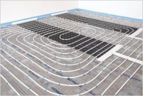
23. Heating pipe layout example
24. Check the air outlet screed protector before installing the screed

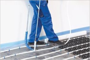
25. Installing the screed
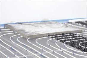
26. Air outlet screed protector after screed installation
27. Removal of the air outlets screed protector
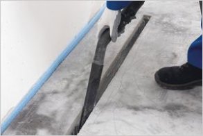
28. Cleaning the air outlet manifold

29. Laying of the floor covering
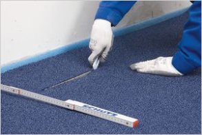
30. Cutting around the air outlet
31. Mounting the slit ventilation profile

32. Installing the profile
33. Screwing down the slit profile…… And done!
Air manifolds and heating circuit manifolds


Pipe layout


| Name | Size | Date | ||
|---|---|---|---|---|
| AIRCONOMY® installation.pdf | 6 MB | 23.06.2015 |


